How to Prepare Inputs for Thermal Network Simulation?
The thermal network tool in CEA simulates thermal and hydraulic losses from network operation. To run the simulation, two input files are required:
edges.shpspecifies the locations of pipes (edges). Each edge is a straight polyline and each end of the edge is connected to a node.nodes.shpspecifies the locations of nodes, which represents the consumers, producers, intersections of streets, and connection points to consumers.
These files can be generated with the Network Layout Tool (cea>technologies>thermal_network>network_layout>main.py) or defined by users, in the later case, the users have to construct the two shape files in the following format:
Example network
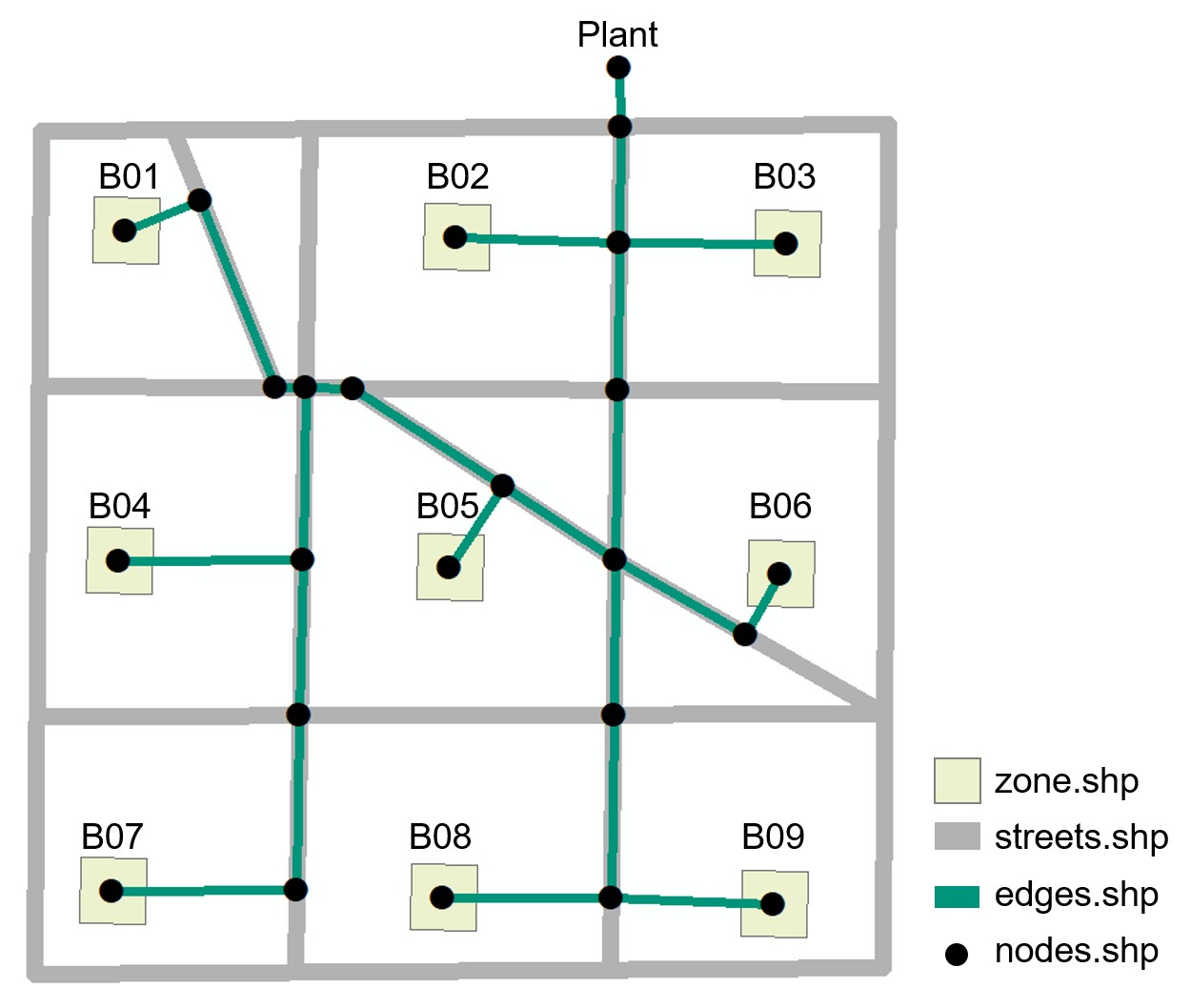
Edges.shp
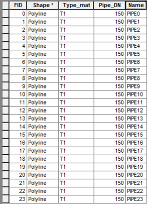
Shape: Polyline (Geometry Type)
Type_mat (String): material of the pipes (default T1), more types can be found in technologies>systems>thermal_networks.xls
Pipe_DN (String): 150 (this is an initial guess, it will be updated after the simulation).
Type (String): Pipe number, the number has to be exactly the same as the FID (use
Field calculatorin ArcGIS, type"PIPE"&[FID]).
Nodes.shp
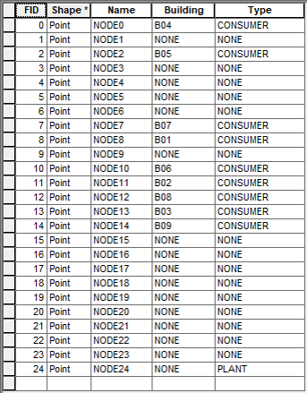
Shape: Point (Geometry Type)
Name (String): Node number, the number has to be exactly the same as the FID (use
Field calculatorin ArcGIS, type"NODE"&[FID]).Building (String): Building number as specified in
zone.shp, or else NONE.Type (String): specify CONSUMER and PLANT nodes, the rest is NONE.
Where to store the file?
The two shape files (nodes.shp & edges.shp) should be kept in either a DH (heating network) or DC (cooling network) folder under this path: your case study\inputs\networks.